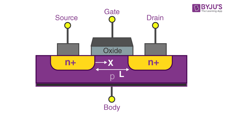


Varying the voltage between the gate and body modulates the conductivity of this layer and thereby controls the current flow between drain and source. The inversion layer provides a channel through which current can pass between source and drain terminals. When a voltage is applied between the gate and body terminals, the electric field generated penetrates through the oxide and creates an inversion layer or channel at the semiconductor-insulator interface. Some companies have started to introduce a high-κ dielectric and metal gate combination in the 45 nanometer node. The gate is separated from the channel by a thin insulating layer, traditionally of silicon dioxide and later of silicon oxynitride. To overcome the increase in power consumption due to gate current leakage, a high-κ dielectric is used instead of silicon dioxide for the gate insulator, while polysilicon is replaced by metal gates (e.g. Research continues on creating insulators with acceptable electrical characteristics on other semiconductor materials. Many semiconductors with better electrical properties than silicon, such as gallium arsenide, do not form good semiconductor-to-insulator interfaces, and thus are not suitable for MOSFETs. Recently, some chip manufacturers, most notably IBM and Intel, have started using an alloy of silicon and germanium ( SiGe) in MOSFET channels. Usually the semiconductor of choice is silicon. Probe pads for two gates and three source/drain nodes are labeled. Photomicrograph of two metal-gate MOSFETs in a test pattern. Nevertheless Kahng pointed out several advantages of the device, notably ease of fabrication and its application in integrated circuits. The device was about 100 times slower than contemporary bipolar transistors and was initially seen as inferior. The principles behind the device were the same as the ones that were tried by Bardeen, Shockley and Brattain in their unsuccessful attempt to build a surface field-effect device. In 1960s, following this research Mohamed Atalla and Dawon Kahng demonstrated a device that had the structure of a modern MOS transistor. Atalla showed that silicon dioxide is very effective in solving the problem of one important class of surface states. Further research showed that silicon dioxide could prevent dopants from diffusing into the silicon wafer. Derick accidentally grew a layer of silicon dioxide over the silicon wafer. The structure failed to show the anticipated effects, due to the problem of surface state: traps on the semiconductor surface that hold electrons immobile. The structure resembling the MOS transistor was proposed by Bell scientists William Shockley, John Bardeen and Walter Houser Brattain, during their investigation that led to discovery of the transistor effect. The basic principle of this kind of transistor was first patented by Julius Edgar Lilienfeld in 1925. Note: threshold voltage for this device lies around 0.45 V History Simulation of formation of inversion channel (electron density) and attainment of threshold voltage (IV) in a nanowire MOSFET. Since MOSFETs can be made with either p-type or n-type semiconductors, complementary pairs of MOS transistors can be used to make switching circuits with very low power consumption, in the form of CMOS logic. The MOSFET is by far the most common transistor in digital circuits, as billions may be included in a memory chip or microprocessor. Similarly, "oxide" in the name can also be a misnomer, as different dielectric materials are used with the aim of obtaining strong channels with smaller applied voltages. The "metal" in the name MOSFET is sometimes a misnomer, because the gate material can be a layer of polysilicon (polycrystalline silicon). In depletion mode transistors, voltage applied at the gate reduces the conductivity. In an enhancement mode MOSFET, voltage applied to the gate terminal increases the conductivity of the device. The main advantage of a MOSFET is that it requires almost no input current to control the load current, when compared with bipolar transistors (bipolar junction transistors/BJTs). Operating as switches, each of these components can sustain a blocking voltage of 120 V in the off state, and can conduct a continuous current of 30 A in the on state, dissipating up to about 100 W and controlling a load of over 2000 W. Two power MOSFETs in D2PAK surface-mount packages.


 0 kommentar(er)
